Sequence diagram
Sequence diagrams show how elements exchange messages with one another as part of an interaction. In contrast to Communication diagrams, in Sequence diagrams the focus is on the chronological sequence of exchanging messages rather than on the channels via which these messages are sent.
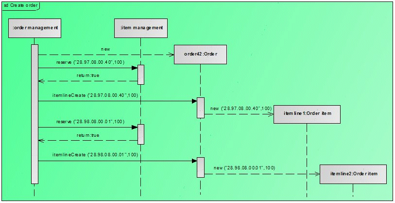
Figure 19 shows the Create order interaction shown in Figure 18 in the form of a Communication diagram as a Sequence diagram. Both diagrams contain elements of the Lifeline type. However, in the Sequence diagram they have an additional dotted vertical line. The name Lifeline can be traced back to this type of graphical representation. The messages are represented by graphical edges in the Sequence diagram.
While the chronological order of the messages is given by their sequence numbers in the Communication diagram, in the Sequence diagram this is defined by their vertical arrangement. The time axis, which is not explicitly visible, runs vertically from top to bottom in the diagram, that is, messages closer to the top are transferred before messages located further down.
The rectangles on the lifelines are elements of the ExecutionSpecification type. They indicate when the object represented by the lifeline is active.