Timing diagram
Timing diagrams show how the state of the elements involved changes when exchanging messages as part of an interaction. The notation is based on corresponding diagrams from digital technology. This diagram type is primarily of interest for modeling of software systems closely related to hardware and has only rudimentary support in ARIS UML Designer 9 and higher.
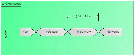
In Figure 20 a simple Timing diagram using compact notation shows the states an order can have. The detailed notation with which the states and their transitions are displayed using timelines is not supported by ARIS UML Designer. The Order states element is an interaction, the :Order element is a lifeline, and the different states are represented using state invariants. The DurationConstraint element also specifies that the delivery state can only last for one to two days.