Activity diagram
Activity diagrams show dynamic processes in the form of a graph of individual actions. They can describe both a process with a high level of abstraction or details of an algorithm in a piece of software.
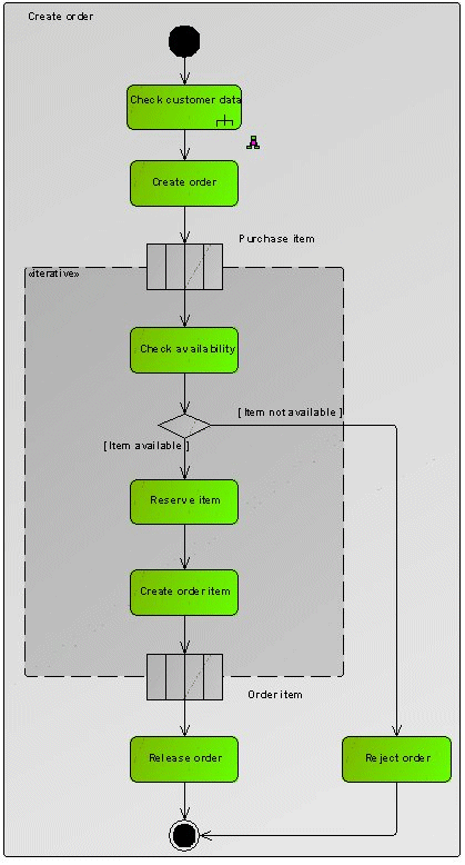
Figure 15 shows the process for creating an order in the form of a UML Activity diagram. The activity starts with an element of the InitialNode type and ends with an element of the ActivityFinal type.
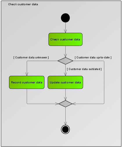
The first step is to check the customer data. This is done using an action of the CallBehaviorAction type. This is an action that in turn invokes an activity Check customer data. This is described in another Activity diagram (see Figure 16).
The other actions are all of the OpaqueAction type. They are characterized by the fact that they are specified by a simple text and have no further UML semantics.
The individual purchase or order items are processed in an ExpansionRegion. This has the customer's purchase items as its input elements and the corresponding order items as its output elements. The ExpansionRegion is run through for each input element.
The relationships in the two Activity diagrams are all of the ControlFlow type. If a text in square brackets is specified on one of these control flow edges, it describes the condition that has to be met for the control flow to proceed along this edge.