Deployment diagram
Deployment diagrams show the assignment of software components to physical IT systems and the networking of these systems with one another.
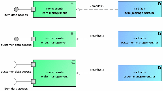
Figure 13 shows the physical manifestation of the components from Figure 7 as JAR files (Java libraries). This is done using UML elements of the Artefact type, which are linked to the corresponding components by a relationship of the Manifestation type.
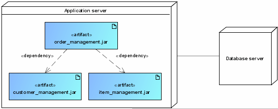
Figure 14 shows how the artefacts or software components defined in Figure 13 are deployed on physical systems and the relationships between these systems.