Protocol State machine diagram
Protocol state machines show the externally observable states and state transitions for a classifier. They define a protocol that the implementations of the relevant classifier must adhere to and show when, in what order, and on which conditions the publicly visible operations for that classifier are invoked.
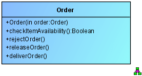
Figure 23 shows the Order class with its public operations (UML elements of Operation type with the property visibility = public, in each case identifiable by the + character at the beginning of the name).
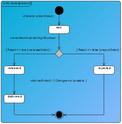
The Protocol state machine diagram in Figure 24 shows how invocations of these operations result in corresponding state changes. Instead of normal state transitions, protocol state transitions are used in protocol state machines.
Protocol state transitions have a different notation than normal state transitions. The notation for a protocol state transition is: [Precondition] Event / [Postcondition]
The precondition is mapped to the preCondition property of the UML type ProtocolTransition, and the postcondition to the postCondition property. As for normal state transitions, the event is mapped to the trigger property, and the triggers are assigned events of the UML type CallEvent, which in turn refer to the corresponding operations for the class, which means that the corresponding operation is displayed as the event in the diagram.