Communication diagram
Communication diagrams show how elements exchange messages with one another as part of an interaction. In contrast to Sequence diagrams, in Communication diagrams the focus is on the channels via which these messages are sent rather than on the chronological sequence of exchanging messages.
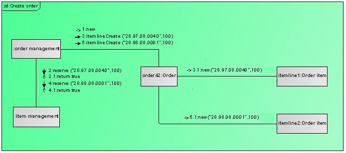
Figure 18 uses a Communication diagram to show how an order is created in the system. The background object that contains all other elements is the interaction itself. The contained elements are elements of the Lifeline type. The term Lifeline comes from its use in Sequence diagrams, where it is represented by a rectangle with a vertical line attached to the bottom.
The lifelines do not show their own names in the diagram, they show the name of the element represented and/or the type name of the element represented. The element represented is assigned to the lifeline through its represents property. Depending on the context, the element represented can be an attribute (property), a port, or a parameter. In the above example a property has been created as an attribute for the interaction for the :Order management lifeline and the Order management component from Figure 6 has been assigned to it as the type. As the name of the attribute is irrelevant here, the lifeline only shows the type name.
The relationships between the lifelines are the connectors familiar from Composite structure diagrams. It is important to note that although they connect the lifelines with one another graphically in the diagram, they are actually relationships between the elements represented. This means that if no represented element is assigned to a lifeline, you cannot connect it to another lifeline in the diagram using a connector.
The messages that the lifelines exchange with one another along the connectors are displayed as text on the connector. An arrow specifies the direction of the message, and the order is given by the sequence numbers of the messages. If the messages have arguments, they are listed in brackets after the message.
This Communication diagram should be read as follows:
1: Order management creates a new order object.
2: Order management reserves 100 items with the item number 28.97.08.0040.
2.1: Item management confirms the reservation.
3: Order management instructs the order object to create a new order item for the item number 28.97.08.0040 with the quantity 100.
3.1: The order object creates a new order item with the corresponding parameters.
4. – 5.1: This process is repeated for another item.
The sequence numbers are automatically calculated in ARIS UML Designer based on the sequence of the messages on the source and target lifelines. If you want to change them, you have to do this in the Properties dialog for the relevant lifelines. Alternatively, you can hide the display of the calculated sequence numbers and assign your own numbers as part of the message name.